Malcolm N. Cooke, Ph.D, Assistant Professor, at the University of Texas at El Paso, requested assistance in designing and manufacturing a custom build tank, cradle, frame, and platform for a 3D Systems’ Viper HA stereolithography machine. Design and manufacture was needed to provide a reduced build volume appropriate for the manufacturing of tissue engineered porous scaffolds using poly (propylene fumarate) (PPF). Reducing the build volume aids in minimizing the volume of PPF resin required to decrease experimental costs, prevent contamination of the diethyl fumarate/PPF resin from the standard stereolithography machine, and has a non-toxic interaction between resin and material.
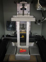
The 3D Systems’ Viper HA stereolithography machine (SLA) used for this project is available for experimental testing using the retro-fitted parts and is located in the William Myron KECK Center for 3D Innovation Laboratory (Figure 1). The newly retro-fitted tank and platform easily supports 10.9 x 11.4 x 5 centimeters biomedical scaffolds. By adding a cradle to the design, the switching of tanks to change the resin type is kept to a minimum. The SLA machine now consists of a cradle which is placed onto the sides of the original 40 liter capacity tank. A reduced tank which has a capacity of 800 grams of resin is placed inside the cradle to ensure stability. The new perforated 10.9 by 11.4 centimeter platform immerses into the tank and moves vertically by aid of a platform frame which is adapted to the original motorized elevator arm.

Figure 1: 3D Systems’ Viper HA SLA
Accepting the opportunity to design and construct a custom build tank, cradle, frame, and platform was simply the beginning process to implement lower cost of experimentation. The new design reduces the volume needed to produce appropriate experimentation of tissue engineered porous scaffolds using PPF. To better understand the concept and importance of this project, a background section is included. A proposal, description of the work product, benefits and feasibility, approach, qualification and references, project costs, and a conclusion are included to provide adequate knowledge of this design project.
2. Background
2.1 History
Stereolithography is the industrial application of liquid solidification of monomers by photo polymerization1. In 1984, 3D Systems was established by Chuck Hull but this system was not approved until 1986. Today, Chuck Hull is considered the father of stereolithography. Use of rapid prototyping
(RP) machines became popular in 1988 when the company 3D Systems of California commercialized the first machine (SLA250) 1. At the time of commercialization stereolithography machines were used for industrial
purposes to model mechanical parts, prototypes and replicas. Use of rapid prototyping machines are now being used for maxillo facial reconstruction, cranio synostosis, skull and maxillo facial tumor surgery, skull plasties, orthodontic surgery, deformities of long bone joints and knee surgery, pelvic fractures, hip dysplasia, spinal trauma, congenital and degenerative spinal
diseases, foot and hand malformations, and in models of soft tissue structures such as the cardiovascular system2.
2.2 Engineering Tissue
The transplantation of natural tissue has been performed several years earlier than implantation of engineering tissue. One problem faced is the lack of donors of living tissues and limited ability of defect reparability to the human body. According to the National Kidney Foundation, more than 89,000 patients are waiting for an organ transplant3. Therefore, implementing engineering tissue has gained higher attention to the biomedical field.
2.3 Scaffolds
Implemented cells are contained inside biodegradable matrices referred to as scaffolds (Figure 2.3.1). Scaffolds are mimicked capsules containing growth factors such as proteins, cells, and synthetic vasculature which are implanted in patients suffering from tissue defects 4. Scaffolds shaped must be
extremely precise to ensure accurate creation when using the stereolithography process (SL). Scaffolds support and guide cells in vivo until regenerated tissue has formed; scaffolds must be biocompatible, biodegradable, and biomimetic. Scaffold shapes must be extremely precise to imitate internal body tissue and show interconnected porosity to allow a natural healing process and produce extra cellular matrix5.

Figure 2.3.1: Scaffolds for Cranial Defects
2.3.1 Scaffold Creation Techniques
2.3.1.1 Fiber Bonding:
Fibers are aligned in shapes of desired scaffolds and then submerged into an evaporative solution. After solvent has evaporated, composites are melted and cooled until fibers are joined.
2.3.1.2 Solvent Casting and Particulate Leaching:
For this method, salt composite membranes are heated above their melting temperatures to yield amorphous or semicrystaline foams.
Advantage
It can be applied to polymers soluble on chloroform or methylene chloride.
It can only produce thin membranes scaffolds.
2.3.1.3 Superstructure Engineering:
Superstructure engineering is a modification of solvent casting and particulate leaching. Scaffold laminates are fabricated using the solvent casing and particulate leaching technique and then bonded together.
Advantage
Disadvantage
Well define structure and spatial organization.
Same type of casting as the solvent casting and particulate leaching technique.
2.3.1.4 Compression Molding:
Mixtures of polymers and porogen are loaded in a mold, heated, and then shaped by being pressed by matched dies6. Porosity is controlled by varying the amount of porogen.
Advantage
Disadvantage
Shapes of the scaffolds can be molded on different shapes depending on the die.
Scaffolds produced may lack mechanical strengths.
2.3.1.5 Extrusion
Composites of polymers and salt is loaded in a mold and then extruded by applying pressure. Salt amounts determine the porosity of the scaffold.
Advantage
Disadvantage
Open pore-structure exists when using the extrusion technique.
Thermal degradation of the polymer occurs.
2.3.1.6 Freeze Drying:
Freeze drying is a process which a polymer is submerged into a solvent, then aqueous solvent is removed from the polymeric material creating foams generally not suitable as scaffolds.
Advantage
Disadvantage
Detailed surface areas.
Not suitable for cell transportation because it produces matrices with varied densities.
2.3.1.7 Phase Separation:
Polymers are dissolved in a solvent and bioactive molecules are added, the mixture is frozen, and finally the solvent is allowed to evaporate leaving a porous scaffold7,
Advantage
Disadvantage
Scaffolds are created with uniform distribution.
One problem is the loss of protein activity.
2.3.1.8 Gas Foaming:
For this technique, disks of polymers created by compression molding or solvent casting are saturated with carbon dioxide which is then expanded creating high porosity foams.
Advantage
Disadvantage
Gas foaming has up to 93% porosity.
High pressure on the detention of activity proteins still need to be assessed.
2.3.1.9 Solid Freeform Fabrication:
Solid freeform fabrication refers to all computer-aided designs such as stereolithography, selective laser sintering, ballistic particle manufacturing, and 3D printing.
Advantage
Disadvantage
Able to form complex shapes.
The amount of resin for the machines used can cost up to
$ 40,000.
2.4 Stereolithography
2.4.1 SL Procedure
The SL procedure is essentially based on elements which are constructed using a photo-curable liquid resin that solidifies once adequately exposed to a laser beam that scans across the surface of the resin. Building is done layer by layer, each layer being 400 micrometers and scanned by the optical scanning system and controlled by an elevation mechanism that lowers at the completion of each layer. Rapid prototyping or the layer by layer formation is a process where each layer adheres to the next layer to form a solid. The bottom layer of the prototype is made first, followed by the successive upper layers, all adhered to each other8. Stereolithography increases the precision of the results by exact contact of the laser by computer direction. Layer manufacturing is one of the most reliable techniques but resulting products average from 3 to 72 hours to complete9.
2.4.2 Operating Cost
Fig. 1 System of SupportsEven though the use of stereolithography has been successful, the 3D Systems’ Viper HA stereolithography machine is equipped with a relatively large resin tank which must be filled during operation. Some of the other tanks, for example in an SLA5000/7000, the estimated worth of the amount of resin required to be kept in the machine can cost up to $ 40,00010. The tank also consumes a large amount of resin that is wasted. Design of a removable smaller custom built tank and build platform will reduce the amount of time and resin when the machine is used to construct 10.95 x 11.43 x 5 centimeter scaffolds. This measurement is similar to scaffolds used for bone ingrowths which require a tank height of only five centimeters and are composed of nanofibers about 8 nanometers in diameter and several micrometers in length11.
2.4.3 Scaffold Supports
Supporting the scaffold is crucial to the design and manufacture in order to ensure the creation of layers will be bound together as upper layers are being constructed. Using a system of supports while the laser beam polymerizes the resin will avoid this problem. This method is also helpful to avoid direct contact with the table surface to aid in removing the scaffold (Figure 2.5.3).

Figure 2.4.3: Scaffold Supports
3. Proposal
The focus of this project was to implement a custom built cradle, tank, build platform, and frame to an original factory 3D Systems’ Viper HA SLA machine. Key issues were to minimize the volume of resin required, prevent contamination of the diethyl fumarate/propylene fumarate resin from the standard SLA machine, and have a non-toxic interaction between resin and material.
The goal of this project was to design and construct a reduced build size suitable for the manufacture of tissue engineered (TE) porous scaffolds using propylene fumarate. To achieve this goal, the following criteria were satisfied (Appendix 10.2):
1. Capable of being retro-fitted to an existing Systems’ Viper HA SLA machine.
2. Easily fitted and removed from existing tank and build table.
3. Tank capacity of approximately 800g (PPF ρ~1.3g/cm ).
4. Maximum build height of 5cm.
5. Build table to be located at focal point of laser (i.e. at same Z axis location as original table at start of build).
6. Custom table to be coupled and driven by existing build table in Z axis.
7. Any components of the assembly in contact with the PPF resin to be made of medical grade stainless steel.
8. Keep mass of assembly to a minimum.
9. Contain no leaks.
10. Smooth, no judder movement of custom table during operation.
11. Assembly needs to be adjustable to ensure custom build table is kept horizontal in the XY plane when moving in Z axis.
3.1 Retro-Fitted
Design and manufacture of the custom built cradle, tank, platform, and platform frame are all retro-fitted to the existing 3D Systems’ Viper HA SLA. No alterations were made to the existing stereolithography machine.
3.2 Installation
Installation of the custom build tank consists of easily placing the fitted cradle lip extensions over the large tank and then placing the fitted tank into the cradle. Installation of the custom build table simply requires attachment of the new platform frame to the elevator arm block.
3.3 Build Height
The build height of the custom reduced volume tank is at the required height of 5cm.
3.4 Tank Capacity
An approximate tank capacity of 800g has been implied. Dimensions obtained were calculated using the required height of 5cm, the poly propylene fumarate density of 1.3g/cm , the medical grade stainless steel density of 8.0 g/cm , and the volume of the new custom build table materials. This has ensured the PPF resin from not overflowing into the pre-existing resin tank. The reduced build volume optimized the quantity of resin, thus reducing the overall cost of experimentation.
3.5 Table Location
The custom table was designed to attach to the elevator block of the original SLA to ensure a smooth vertical movement. The point at which the focal point of the laser comes in contact with the Z axis of the original platform is measured to exist at the center of the reduced size tank. These measurements aided to verify the exact placement of the new table.
3.6 Table Requirements
The custom build table is driven by the existing elevator block. Prior to constructing the custom table, two designs were considered to fill this specification.
3.6.1 Design 1
The custom build table was designed to fasten to the elevator arms to employ a vertical movement driven by the motored elevator.
3.6.2 Design 2
The custom build table was designed to fasten to the holes of the existing platform to employ a vertical movement driven by the motored elevator.
3.7 Material Specification
All materials which will interact with the PPF have been constructed using a medical grade stainless steel (316 LVM). The 316 LVM is vacuum melted to achieve the extremely high levels of purity and “cleanliness” required for surgical implants12, producing a non-toxic interaction between the resin and materials. With the use of this medical grade stainless steel no cracks of fatigue fracture will occur from either internally or on the surface13.
3.8 Assembly
Assembly specifications were designed to require only one person to install and remove the custom build tank, cradle, frame, and platform. This ensures a quick and easy one person assembly saving cost by keeping machine shutdown to a minimum.
3.9 Sealing
The custom built tanks were melted together at the seams to guarantee a 316 medical grade stainless steel product. Leak tests were also conducted to the custom build tank after it was sealed to ensure resin remains in place and leaks never occur.
3.10 Operation Requirements
During operation there is no unwanted movement from the build table to ensure precise operation. The vertical movement of the platform frame and platform is smooth since it is driven by the original elevator block.
3.11 Adjustable Assembly
Assembly of the custom build table is adjustable on the platform frame to ensure a perfectly level build table during movement in the Z direction. This is essential for accurate tissue engineered porous scaffolds.
4. Design Plan
4.1 Benefits and Feasibility of the Product
Rewards of building the custom built tank and platform reflect experimental cost as well as practicability of installation. PPF resin will be used to conduct the manufactured scaffolds for the tissue engineering. PPF is extremely expensive therefore a reduced tank volume of approximately 800 grams minimizes this cost. Since the custom built platform and tank is easily installed and removed from the existing 3D Systems’ Viper HA SLA machine, it is not necessary to buy an additional SLA machine or alter the existing one. The ergonomic aspect of the tank and cradle design allows the tank itself to be removed from the machine when not in used without the necessity of any tools. In addition, the frame design allows the platform to be removable without detaching the frame from the motored elevator block.
4.2 Approach
The 3D Systems’ Viper HA rapid prototyping machine consists of a rectangular tank and a platform which is the building table for scaffolds used in the biomedical field. Holes in the table act as a rough table surface to help stabilize the scaffold support. The building table is centered with respect to the resin tank and initially located directly above it. Once operation begins a laser beam, adapted with a mirror system and directed using a computer, hits the desired points to polymerize the resin and create an exact replica of the model. The current 3D Systems’ Viper machine is supplied with a level sensor that scans the resin to assure the machine as a whole is level, this aiding to the preciseness of the scaffolding. A resin blade is also supplied that wipes the
surface after each level of laser contact to ensure every layer on the model corresponds to the design.

Figure 4.2.1: SLA Components
Accordingly to the specifications for this project, the new design is much smaller to minimize resin surpluses. The way to approach a manageable, ergonomic yet elementary design of the new tank was thought out carefully during the conception of the project. A cradle was designed to attach to the walls of the original tank. This innovation allows the tank to be easily fitted and removed from the SLA machine.
The custom build platform was designed to be centered in z axis and capable of up and down movement, but fixed in the XY axis to ensure no movement in the XY direction. Design of the custom build platform allows the platform frame to attach to the elevator block of the existing SLA machine to ensure stability.
Mass of assembly of the new design allows the smaller platform to be driven by the elevator block. This design disregards the need of using the existing platform as a guide and consequently minimizes the weight supported by the
machine. Additionally, the design of the new platform enables the user to remove the table without detaching the platform frame from the elevator block.
Optimization methods were used in some applications to modify current estimates. These methods were adopted to reduce necessary material by means of mathematical calculations to determine economical designs (Appendix 10.3).
Models of the reduced in volume tank and building platform were designed using Unigraphics NX 3.0, a computer aided design program utilized to visualize the movement and assembly of real products (appendix 10.4). Models were then represented out of cardboard to contemplate the design in actual dimensions. These models were then used as layouts to start with the actual machining of the design.
The prototype was built using medical grade stainless steel instead of vanadium steel because it is a stronger material, highly resistant to corrosion, and is very ductile10. The custom build tank was melted and welded to assure sealing.
4.3 Description of Work Product
For this project a 12.7x 12.7 x 5 centimeter tank was designed, as well as a 10.9 x 11.4 centimeter platform. As previously explained in the proposal section the project followed certain criteria and satisfied all conditions which are the new components of the stereolithography machine.
Purposes of this project were to add a custom built tank and platform to an already existing 3D Systems’ Viper HA stereolithography machine without
altering it. Different approaches and ideas of designed parts were modeled using the Unigraphics program, NX 3.0. Two different designs met the
specified criteria needed to provide logical outcomes. The platform was required to be driven simultaneously with the existing platform. Mass assembly has been kept to a minimum enabling the elevator block to lift the custom platform.
5. Design Variants
5.1 First Design
The first design was created attaching the arms of the custom build platform to the arms of the existing platform. Figure 5.1.1 illustrates the entire model with the design of the new custom built tank and platform. The custom 12.7 x 12.7 x 5 centimeter tank is shown in green, which sits on the rim of the original 40 liter tank. The motor moves the existing platform in the z-direction and the custom platform will follow the same movement. As the original table is either raised or lowered, the custom platform will rise or lower in conjunction with the original platform.

Figure 5.1.1: First Design
Figure 5.1.2 depicts the custom built tank located on the original tank. The custom tank was accurately installed to ensure the location of the platform is at the same z-axis location as the existing platform. From this figure it can also be observed that the custom table fits perfectly into the custom container leaving 0.32 centimeters of clearance.
Custom Platform

Figure 5.1.2: Side View of Custom Tank and Platform


Figure 5.1.3: Top View of Custom Tank and Platform

Figure 5.1.4: Side View of the Model
5.2 Second Design
Knowing the position of the custom platform, the second designs’ aspect was derived by adding extensions to the custom platform which is inserted through the holes of the existing platform. Using NX 3.0 software, designs are expressed in detail of the smaller platform fitting into the original platform (Figure 5.2.1). The design was formed using the base of first custom platform design, but modified at the arms. Arms of the custom platform bend in the y- direction, then into the negative z- direction.
Figure 5.2.1: Side View of the Second Design
The following illustration shows the custom platform attached to the original platform. As shown, there are cylindrical pins which slot into the original platforms’ holes.
Figure 5.2.2: Bottom View of the Second Design
5.3 Selection of the Design
Two designs were constructed prior to fabrication of the custom build platform. To decide whether the first or second design would be most ideal, a selection process was implicated. A system of rank was formed to single out the best design for this project (Appendix 10.6). Design one was selected, having met all required criteria and showed more feasibility.
5.4 Design Modifications
5.4.1 Design Modifications of the Platform
Modifications were made to the selected design due to the advantage of disregarding the original platform. Instead of attaching the platform frame to the original platform, the elevator block was more appealing. The elevator block has pre-drilled holes for easy installation of the platform frame shown in Figure 5.4.1.
Figure 5.4.1: Second Design for Custom Build Platform
5.4.2 Design Modifications of the Tank
Design modifications of the custom built tank resulted in fabrication of a tank cradle. Implementing the cradle added the advantage of using multiple resin tanks to build scaffolds of different resin types. Resin tanks are simply installed by setting them into the cradle. Lips of the tanks sit on sides of the cradle and lips of the cradle are placed over the sides of the original tank (Figure 5.4.2)
Figure 5.4.2: Custom Build Cradle and Tank Lips
6. Final Design
6.1 Modeling and Machining
Two custom built tanks were constructed for this project. Top and side views the CAD design (Figure 6.1.1), were utilized to construct a model out of cardboard for the tank (Figure 6.1.2). The cardboard prototype constructed was the same thickness of the 316 medical grade stainless steel required for the manufactured tanks and cradle.
Figure 6.1.1: Top and Side Views of the CAD Design for the Tank
Figure 6.1.2: Top and Side View of the Tank
Only one cradle was fabricated for this project, modeling and manufacture of the cradle followed the same pattern as the tank. From the top and side views (Figure 6.1.3), a model made out of the previously mentioned cardboard was constructed (Figure 6.1.4).
Figure 6.1.3: Top and Side Views of the CAD Design for the Cradle
Figure 6.1.4: Top and Side View of the Cradle
After the cardboard models were completed, the tank was place into the cradle to assure a perfect fit and consequently the cradle was tested on the original SLA machine to verify the dimensions. Once dimensions were confirmed by testing, models were unfolded and used as layouts to cut the pattern out of the specific grade of stainless steel and start machining.
Construction of the platform required drilling of 388 holes; therefore a CAD design was necessary. Design of the platform was modeled using SolidWorks which then allowed the design to be imported to Feature CAM (Figure 6.1.5). Feature CAM software is required to run the numerical program, thus the
CNC machine can operate and drill the holes precisely maintaining a slow speed (Figure 6.1.6). However, certain problems were encountered. Bending
of the platform resulted from high pressure forced by the CNC machine. A milling machine was the used to manually drill the holes to conclude machining.
Figure 6.1.5: CAD Design for Platform Figure 6.1.6: CAD Design Imported to
FeatureCAM
Two different materials were used to machine the frame. The arms and base of the frame were constructed using 316 medical grade stainless steel. These were welded together to ensure a horizontal platform position. Black steel flat bar was used for the top structure of the frame which was also welded to the arms.
Figure 6.1.7: Top and Side Views of the CAD Design for the Frame
6.2 Final Design Concept
As a final prototype, one frame, one cradle, two tanks and two platforms were built. Every part which comes in contact with resin was fabricated using 316 medical grade stainless steel required to result in non-toxic interaction between the resin and material. Parts include the arms and base of the platform frame, two platforms, and two tanks. Since the cradle and top flat bar of the frame will not come in contact with the resin, they were constructed using 308 stainless steel and black steel respectively.
Figure 6.2.1: Final Prototype
6.2.1 Installation
Positioning of the cradle, to the center of the 40 liter tank, began the installation process. Foam was attached to the lips of the cradle to guarantee a stable and centered position. Once the cradle was placed and measured, the tank was placed into it.
Figure 6.2.1.1 Cradle Installation
A groove at the bottom of the platform frame allows the platform to slide into it and is then fixed by two nylon threaded screws. The platform frame was leveled by adjusting the 1 inch oblong slots which are attached to the elevator block of the SLA machine. Once the platform frame was leveled, the threads were tied to ensure stability.
Figure 6.2.1.2: Platform and Platform Frame Installation
6.3 Qualifications and references
Completion of the design and manufacture of the custom built cradle, tank, platform, and platform frame for the 3D Systems’ Viper HA Stereolithography machine required research, design, and engineering of experienced mechanical engineering students. These students were able to perform and satisfy the criteria necessary to arise with a successful outcome. The resumes of Richard Bustamante, Sarah Anita Gardiner, Flor Manriquez and Elvia Renova are attached in appendix 10.8.
7. Schedule
Weekly schedules and responsibilities were recorded in a Gantt chart to complete the project in a timely matter. Tasks, duration, start and finish dates, and activity dependency which were followed to successfully complete the project are illustrated (Figure 7.1). Activity on arrow notation was implicated to create a network of activity, duration, and procedure (Appendix 10.9).
Figure 7.1 – Gantt Chart
8. Costs
Cost estimates were based on the price of materials and billable hours. The price estimate for 316L Stainless Steel was $2.95/pound14. Billable hours for engineering research, design, labor, etc. is $50/hour. Billable hours for machine operation run $50/hour. Once actual purchasing of materials and shop work began, the cost estimates were dismissed. Distributors of medical grade stainless steel located in the
El Paso area are rare (Appendix 10.10). The only two companies which carry it are Allsteel Fabrications and World Metals. The 16 gauge 316 stainless steel sheet needed to fabricate the two tanks was $90 and purchased at World Metals. World Metals also donated two 8 gauge 316 stainless steel plates which were used to machine the two platforms. To machine the two platforms, drill bits were purchased from Home Depot costing a total of $124. The cradle was fabricated using a 16 gauge 308 stainless steel which was donated from Allsteel Fabrications. World Metals also donated an 8 gauge 316 stainless steel plate and 8 gauge 316 stainless steel flat bars which were used to construct the platform frame. Finally the black steel flat bar used to adapt the platform frame to the original elevator block was donated from Allsteel Fabrications. Fabrication of the cradle, two tanks, and platform frame was at Allsteel Fabrications and all machine operating hourly costs were donated. Machining of the two platforms was at El Paso Community College and The University of Texas at El Paso and all machine operating hourly costs were donated.
Table 8.1: Estimated Cost
316L Stainless Steel (plate, sheet, bar)
$440.00
Billable Engineering Hours (20 hours/week/person)
$28,000.00
Billable Machining Hours (SLA Testing of Operation-5 hours)
$250.00
Billable Machining Hours (Fabrication-30 hours)
$1,500
Miscellaneous (316 welding material, nuts & bolts)
$50.00
Total
$30,240.00
Table 8.2: Actual Cost
316L Stainless Steel (Sheet for Tanks)
$90.00
Billable Engineering Hours (20 hours/week/person)
Donated
Billable Machining Hours (SLA Testing of Operation-5 hours)
Donated
Billable Machining Hours (Fabrication-120 hours)
Donated
Miscellaneous (Foam Tape)
$5.00
Miscellaneous (Drill Bits)
$124.00
Miscellaneous (Nylon Screws)
$3.00
Total
$222.00
Table 8.3: Donated Materials/ Hours
Materials/ Billable Hours
Business
308 Stainless Steel 16 Gauge Sheet (Cradle)
Allsteel Fabrications
316 Stainless Steel 8 Gauge Plate (Tables)
World Metals
316 Stainless Steel 8 Gauge Bars (Frame)
World Metals
Black Steel Flat Bar (Frame)
Allsteel Fabrications
Billable Engineering Hours (20 hours/week/person)
Senior Design Students
Billable Machining Hours (SLA Testing of Operation)
KECK Lab
Billable Machining Hours (Fabrication-120 hours)
EPCC, UTEP, Allsteel Fabrications
9. Conclusion
Design and manufacture of the custom built cradle, tank, platform, and platform frame for the 3D Systems’ Viper HA stereolithography machine was completed November 22, 2006. The 3D Systems’ Viper HA stereolithograpy machine is now retro-fitted and equipped with all the newly fabricated parts. No alterations were made to the original SLA machine ensuring that scaffolds can be built using the 40 Kg tank if needed in the future. Scaffolds can now be produced using the 800 gram tanks which allow the operator to create scaffolds using different types of resin without having to discard the previous used resin. The reduced build volume of the custom built cradle, tank, platform, and platform frame saves production cost of scaffolds, aids in minimizing the volume of resin required, prevents contamination of the diethyl fumarate/propylene fumarate resin from the standard stereolithography machine, and has a non-toxic interaction between resin and material.
Since the original tank consumes approximately $40,000 worth of polypropylene fumarate resin; this aiding the new tank to significantly reduce resin consumption by 96% producing a cost of $1781. The budget to design
and manufacture the cradle, two tanks, two platforms, and platform frame was $300; the actual cost of the final product was $222.
Completion of the design and manufacture of the custom built cradle, tanks, platforms, and platform frame for the 3D Systems’ Viper HA stereolithography machine required research, design, and engineering of
experienced mechanical engineering students and was completed ahead of schedule and under budget. Thank you.
10. Appendices
10.1 Research
10.1.1 Bibliography
1 Andreas Gebhardt, 2003, Rapid Prototyping, 1st Edition, Carl Hanser Verlag, Munich, pp. 82-89.
2 Parphivan J., Abirami O., Murugan A., Rabhakrishnan R., 2004, “Custom Cranioplasty using Rapid Prototyping Technology”, Journal of Neurology India, vol.52 (4) pp. 520.
3 National Kidney Foundation, 2005, “25 Facts About Organ Donation and Transplantation,”
4 Buddy D. Ratner, Allan S. Hoffman, Frederick J. Schoen, Jack E. Lemons, 2004, Biomaterials Science, 2nd Edition, Elsevier, California, pp. 744-750.
5 Manjuabala, 2005, “Biomimetic mineral-organic composite scaffolds with controlled internal architecture,” Journal of Material Science 16 pp. 1111-1119
6Jeff Butcher, Dec. 04 2003, “Compression Molding,” Ball State University.
7Berger S., Guaqueta C.,Ilievski F & Mak J. “Processing,”
8 Rafiq Noorani, 2006, Rapid Prototyping Principles and Applications, 1st Edition, John Wiley & Sons, Inc., Hoboken, New Jersey, pp. 57-79
9 Wikipedia, March 2006 . “Rapid Prototyping,”
10 Joon B. Park, Joseph D. Bronzino, 2003, Biomaterials-Principles and Applications, 1st Edition, CRC Press, Boca Raton, London, New York, Washington, D.C., pp.2-3
11 Neelina H. Malsch, 2005, Biomedical Nanotechnology, 1st Edition, CRC Press Taylor and Francis group, Boca Raton, FL., pp. 179
12Narrowboat Way, Hurst Business Park, Brierly Hill, West Midlands “Alloy Wire International,”
13 Masaki K, Ochi Y., Matsumura T., 2004, “ Initiation and propagation behavior of fatigue cracks in hard-shot peened Type 316L steel in high cycle fatigue”, Fatigue & Fracture of Engineering Materials & Structure vol. 27. pp 1137-1145.
14 Bill Victory (Vice president), Samuel, Sons &Co. Inc.
email:corporate@samuel.com
Tel: (800) 267-2683
Fax: (905) 279-9658
Location: Ontario, Canada.
10.1.2 References
Linda G. Griffith, Gail Naughton, 2002, “Tissue Engineering- Current Challenges and Expanding Opportunities”, Journal of Science Magazine Vol. 295. no. 5557 pp. 1009 – 1014
Malcolm N. Cooke, John P. Fisher, David Dean, Clare Rimnac, Antonios G. Mikos, 2002, “Use of Stereolithography to Manufacture Critical-Sized 3D Biodegradable Scaffolds for Bone Ingrowth”, Wiley Periodicals, Inc. Journal of Biomedical Materials Research. Part B, Applied Biomaterials 64B: 65-69, 2002.
Beer, David and David McMurrey(2004) A Guide of Writing as an Engineer, 2nd Edition, John Wiley and Sons, Inc. New York, pp. 103-106
Clark, Wallace (1922) The Chart: a Working Tool of Management, 1st Edition, Ronald Press Co. New York, pp.10
MSOE Rapid Prototyping Center, June 12, 2006. “Rapid Prototyping Manufacturing” http://www.msoe.edu/rpc/graphics/sla_process.gif, Accessed on September 15, 2006.
Samuel, “Product Locator: a leader in the Metals Industry”, Since 1855, http://www.samuel.com/locator/main_locator.php?process=&from=reset, Accessed on September 17,2006.
Rafiq Noorani, 2006, Rapid Prototyping Principles and Applications, 1st Edition, John Wiley & Sons, Inc., Hoboken, New Jersey, pp. 57-79
10.2 Original Criteria
Senior Design
Design and Manufacture of a Custom Build Tank for a 3D Systems’ Viper HA Stereolithography Machine
Background
A custom build tank is required to be retro-fitted to an existing 3D Systems’ Viper HA stereolithography machine (SLA). The custom build tank will provide a reduced build volume suitable for the manufacture of tissue engineered (TE) porous scaffolds using poly (propylene fumarate) (PPF). The TE scaffolds will provide a bio-active environment to encourage and promote bone ingrowths for the repair of cranial defects.
Design Criteria
The custom build tank must satisfy the following criteria:
Capable of being retro-fitted to an existing Viper HA SLA machine.
Easily fitted and removed from existing tank and build table.
Tank capacity of approximately 800g (PPF ρ~1.3g/cm ).
Maximum build height of 5cm.
Build table to be located at focal point of laser (i.e. at same Z axis location as original table at start of build).
Custom table to be coupled and driven by existing build table in Z axis.
Any components of the assembly in contact with the PPF resin to be made of medical grade stainless steel.
Keep mass of assembly to a minimum.
No Leaks!
Smooth, no udder movement of custom table during operation.
Assembly needs to adjustable to ensure custom build table is kept horizontal in the XY plane when moving in Z axis.
10.4 Programs Used
10.4.1 Unigraphics NX 3.0
NX is a next-generation digital product development system that helps companies transform to product lifecycle. Providing a complete suite of integrated process automation tools, NX enables companies to capture and reuse product and process knowledge. NX 3.0 was used in this project to design and model all custom parts, including the SLA machine.
http://www.ugs.com/products/nx/
1o.4.2 Solid Works
Solid Works is software proven in production across a broad range of industries, which allow product designers and manufacturers to obtain quality products to market faster at a lower cost. It was not viable to import the NX 3.0 file for the custom table platform to the CNC machine. Therefore, the part was remodeled using the Solid Works program.
http://www.solidworks.com/pages/successes/industry_solutions/Industry_Solutions.html
10.4.3 Feature CAM
FeatureCAM is a suite of CAD/CAM software combining cutting edge technology with simplicity. FeatureCAM automatically calculates feeds and speeds to determine roughing and finishing operations. For this project, Feature CAM was used to create nylon prototypes. The custom platform model was imported from Solid Works.
http://www.featurecam.com/
Art Beltran (Sales Associate), World Metals.
Email: artbeltran@sbcglobal.net
Tel: (915) 759-7515
Fax: (915) 759-7516
Location: 3733 Shell St. Suite F
El Paso, TX 79925
John Escareno (Sales Associate), World Metals.
Email: john.escareno@sbcglobal.net
Tel: (915) 759-7515
Fax: (915) 759-7516
Location: 3733 Shell St. Suite F
El Paso, TX 79925
Robert Arias (President), Allsteel Fabrications.
Tel: (915) 566-3986
Fax: (915) 566-4200
Location: 720 North Copia
El Paso, TX 79903
Rick Schaffino (Manager), Allsteel Fabrications.
Tel: (915) 566-3986
Fax: (915) 566-4200
Location: 720 North Copia
El Paso, TX 79903
Dr. Malcolm Cooke (Assistant Professor), University of Texas at El Paso
Email: mcooke@utep.edu
Tel: (915) 747-5000
Location: 500 University Ave.
El Paso, TX 79968
Angel Lerma (MACH Tech. Instructor), El Paso Community College
Email: angell@epcc.edu
Tel: (915) 831-2362
Location: Advanced Technology Center
P.O. Box 20500
El Paso, TX 79998